Not to taunt faith, but all technical difficulties are resolved! Also: graph of data flow and their representations.
A lot has happened since a proper updated:
- I received the Xsens cable I asked for. The CA-USB2-MTI cable has a PicoBlade header. Tijs of UvA’s Technical Service made me a simpler connector than described in an earlier post. This one only connects the wires required for USB and the SyncOut to a SMB plug.
- Capture on
SyncInon the camera works. - Sending a signal over SyncOut with the IMU finally works. In the Xsens’s MT SDK you have to tell over which line you want to do some synchronization. I choose for the
XSL_Out1line, because it „Applies to Awinda Station and Mt” according to the SDK’s documentation. I assumed „Mt” stands for any MTx or MTi device. That seemed to be wrong, and I needed to use theXSL_Bi1Outline. Problem: Camera does not react to a signal. Possible reasons:- Camera software is not configured right. I know it is capable of capturing on signal, but I forgot to document the right settings. However, the current settings seemed to make sense. Quick test: change settings in RQT. Some of these should react to a signal. However, none reacted. Probably not the main problem, then.
- The wire between the SMB and PicoBlade is not connected correctly. Test to see if there is any signal at all coming from the
SyncOutwire. I cut off the crimp protecting the connector to the PicoBlade. By doing so, I could attach an oscilloscope to theSyncOutandGNDwires. The oscilloscope showed a lot of noise around 1.5 V. As the line should have a high signal at > 2.9 V, this (probably) indicated real noise. This makes the case that the SMB-PicoBlade wire is wrongly connected less probable. - The signal is not coming through the wire, because the wire is incomplete/broken/whatever.
I reconnected the oscilloscope in the same way as above. Now I also hooked up a function generator to the Fischer header’s pin 6 (connected to the
SyncOutwire). The function generator was to generate a block function, and I saw that one on the oscilloscope. This is not the case. - The wrong line is selected in the MT SDK. I tried some different values which also mention
Outin their name.XSL_Bi1Outgave the following output on the oscilloscope:
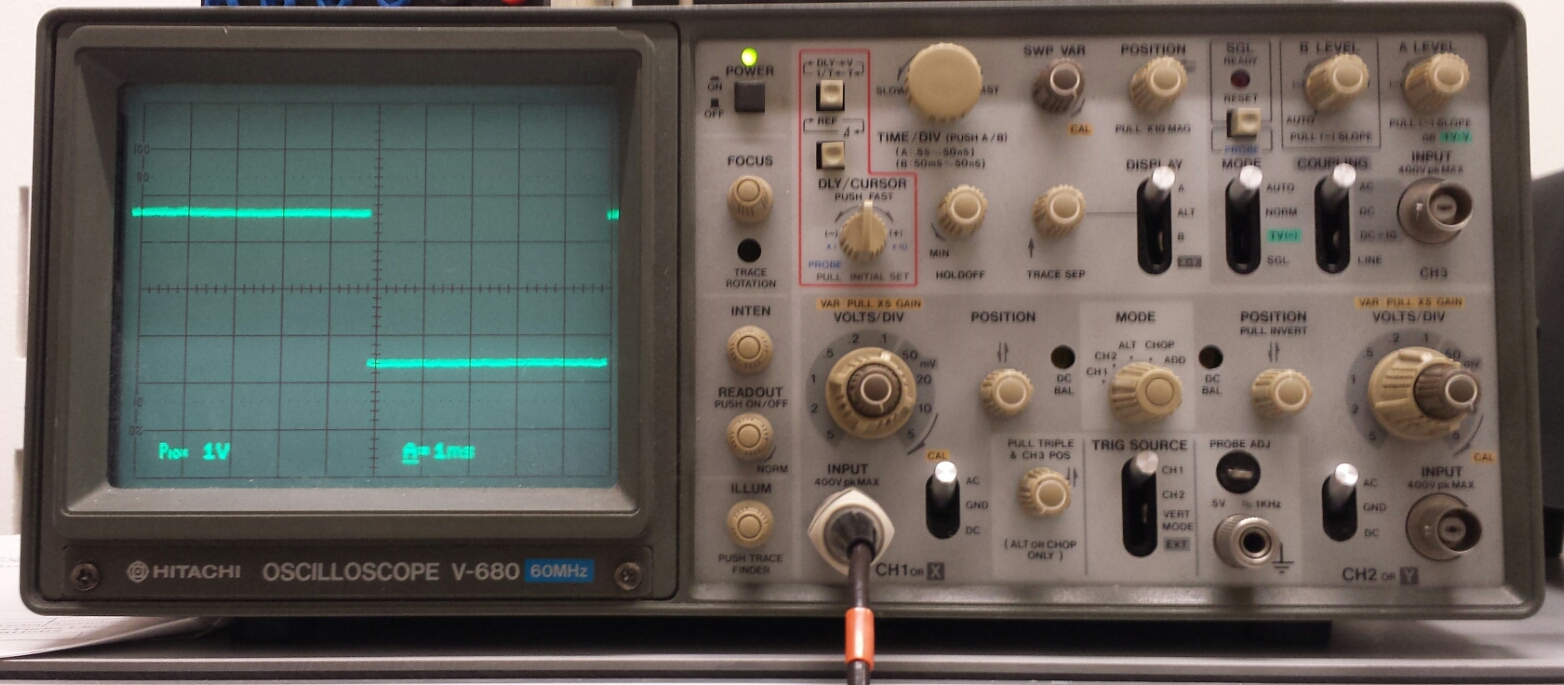
Oscilloscope shows the long sought after block pattern.
- To get a better idea of where I am standing in my thesis development, I made a graph of how data should flow. See the figure for explanation. The „Marker-based pose estimator” (provided by pal_robotics/aruco_ros needs some testing. The „Bleser’s method” and „GP:Learn” nodes still need to be implemented.

Diagram representing the data flow of the system considered in this thesis. Nodes represent clearly separable pieces of code. Arrows indicate data flowing from one node to another. Edge labels in monospaced text indicate the exact ROS messages to be transferred. Edge labels in bold are uncertain (because I need to read more). A dotted edge is a hardware connection between two devices. A dashed, transparant node is some piece of code outside the scope of this project.